In addition to providing commercial communications services, 5G NR Jamming, spoofing and sniffing of cellular networks are used to broadcast emergency information, announcing natural disasters and other crises. As we have seen with LTE, despite being designed for commercial communications. The latest cellular technology is often utilized for mission-critical applications such as public safety and military communications. Recently, the Third Generation Partnership Project (3GPP) released the specifications for 5G New Radio (NR). This which is expected to be the primary 5G standard moving forward. Unfortunately, like any wireless technology, disruption through deliberate radio frequency (RF) interference, or jamming, is possible. Just as we have become dependent on LTE, over the next decade we will likely become dependent on 5G NR. Thus is why we must ensure it is secure and available when and where it is needed.
More specifically, the number of slots per frame is a function of the subcarrier spacing, which varies between 15 and 240 kHz. The uplink (UL), however, has the option between normal OFDM just like the downlink, or DFT spread OFDM (DFTs-OFDM). This is essentially the same that LTE uses in its uplink.
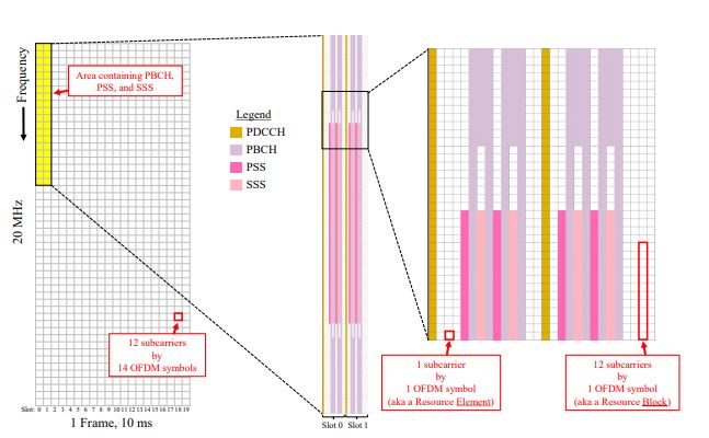
Similar to LTE, a Resource Element (RE) is one subcarrier by one OFDM symbol. Similar to LTE, every frame is 10 ms long in duration. there are 10 subframes in one frame, and there are 14 OFDM symbols in a slot.
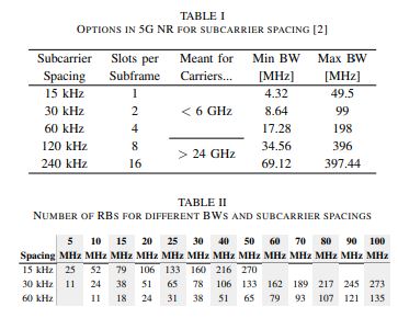
Table II indicates the number of RBs as a function of system bandwidth and subcarrier spacing when below 6 GHz. The 5G NR frame structure is similar to LTE, but incorporates much more flexibility and includes some important modifications.
As with LTE, the downlink (DL) uses standard orthogonal frequency-division multiplexing (OFDM) with a cyclic prefix. A major difference is that the number of slots per subframe (which was always equal to two in LTE), is now variable.
Unlike LTE, the Resource Block (RB) is 12 subcarriers by 1 OFDM symbol.
Figure 2 shows an example of the downlink frame.
5G NR is operable from below 1 GHz to 100 GHz, making it the first generation of cellular technology with such a flexible frequency range.
5G NR supports frequency division duplexing (FDD) and time division duplexing (TDD).
The DFT-s-OFDM mode does not support multi-stream transmissions and is intended for coverage-limited cases [1].
The 5G NR architecture is composed of components of LTE combined with a new radio access technology that is not backwards compatible with LTE.
In Table I we list the different options and the carrier frequencies they are designed for.
The information carried on the PBCH is known as the Master Information Block (MIB). Which includes parameters such as the subcarrier spacing, position of downlink reference signals, and the position of downlink control channel.
Physical Uplink Control Channel The Physical Uplink Control Channel (PUCCH) is used by the UE to send the base station a variety of control information, including hybrid-ARQ acknowledgments, scheduling requests, and channel state information [9].
5g NR Jamming and Spoofing Vulnerability of the PBCH:
The symbols assigned to the PBCH region are all within two or four slots of each other (depending on whether the carrier is below or above 3 GHz respectively). A jammer selectively targeting the PBCH will appear to have a very low duty cycle, especially at the higher subcarrier spacings. Where the duration of one slot is lower.
Downlink and Uplink User Data The Physical Downlink Shared Channel (PDSCH) and Physical Uplink Shared Channel (PUSCH). They are used to transmit user data from the base station to the UE and vice versa, and represent the bulk of the frame.
Physical Downlink Control Channel The Physical Downlink Control Channel (PDCCH) is used to send control information to the UEs on a per-slot basis.
The extent to which a physical channel or signal is vulnerable to jamming is highly influenced by the sparsity of that channel/signal with respect to the entire time-frequency resource grid [3].
PHYSICAL LAYER VULNERABILITIES OF 5G NR
This section analyzes each specific physical channel and signal of 5G NR, according to 3GPP Release 15, to determine how vulnerable it is to jamming and spoofing.
The effectiveness of a downlink PT-RS jamming attack is not clear using the information currently available, because we would need to know how often PT-RS are enabled in practice, and what density the base station vendors decide to use as a default.
A jammer designed to jam the PSS and/or SSS selectively in time has to synchronize to the cell in time, and identify the subcarrier spacing (which might already be known beforehand using publicly available band plans).
By jamming the PBCH, UEs will not be able to access critical information they need to connect to a cell, thus preventing new UEs from accessing one or more cells.
As described in [6], the SIB messages provide information such as the idle timer configuration of the network, unique identifiers of the cell, and the RB mapping of critical control channels.
In addition, there is the Phase-tracking RS (PT-RS) for the PDSCH and PUSCH, Channel state information RS (CSI-RS) for the downlink, and Sounding RS (SRS) for the uplink [2].
While surgically jamming these channels is possible, the adversary might as well jam the entire uplink or downlink signal (and hence this is what we show in Figure 3).
This latter approach involves jamming 240 subcarriers, and to provide some perspective, a 20 MHz downlink using 15 kHz subcarrier spacing has 1272 subcarriers.
Similar to LTE, uplink control information can also be carried on the PUSCH, meaning jamming just the PUCCH will not block all uplink control information.
Synchronization Signals Similar to LTE, 5G NR contains a Primary Synchronization Signal (PSS) and Secondary Synchronization Signal (SSS) which together are used for frame/slot/symbol timing as well as conveying the Physical Cell ID.
Unlike LTE, Demodulation RS (DM-RS) are separated by physical channel, because 5G NR does not include cell specific reference signals.
It is also possible to jam the DM-RS for the PBCH without needing to synchronize to the cell, by jamming the correct 60 subcarriers.
The DM-RS for the PBCH fits the bill, because it is in the same spot every frame and only requires knowledge of the cell ID and where the PBCH is located, which can easily be known if the jammer is already able to time-synchronize to the frame.
While the MIB message contains essential PHY layer configuration necessary by the UE to establish a radio link with a cell, the SIB messages contain detailed information on the configuration of the cell and overall network.
PBCH jamming can be performed in a time-selective manner if the jammer can synchronize to the target cell.
A factor that reduces the vulnerability of a channel/signal is whether it is mapped to the time-frequency resource grid using a dynamic scheme that involves higher layer parameters (that a jammer may not know).
In order to jam all possible locations the PDCCH might reside in, assuming knowledge of CORESET-freq-dom, the jammer would have to jam every subcarrier, using a duty cycle of either 7%, 14%, or 21% depending on the value of CORESET-time-dur.
An example of the 5G NR downlink signal frame structure for a 20 MHz signal with 30 kHz subcarrier spacing, using a carrier below 3 GHz.
Further details are included in the SIB messages which provide information on the received power thresholds that trigger a handover to another cell and similar mobility actions.
Physical Broadcast Channel The Physical Broadcast Channel (PBCH) is transmitted in the same slots as the PSS and SSS, an example of which is shown in Figure 2.
Otherwise, the jammer could simply jam the subcarriers the PBCH is on using 100% duty cycle.
There are five different PUCCH formats, and there are a variety of parameters provided by the higher layer to inform the UE about which subcarriers and symbols to transmit each PUCCH message on.
The PBCH region spans more subcarriers than the PSS/SSS; it occupies 240 subcarriers, across 12 OFDM symbols for a carrier below 3 GHz, and 24 symbols for a carrier above 3 GHz.