What is an RF jammer, and how does it work? Radio jamming is a deliberate jamming, blocking or interference with authorized wireless communications. The concept can be used in wireless data network to disrupt information flow, thus this include particular radio or satellite network. As a result of RF signal jamming, the desired wireless signal cannot be received or decoded properly at the wireless receiver station.
Jamming is usually distinguished from interference that can occur due to device malfunctions or other accidental circumstances. Devices that simply cause interference are regulated differently. Unintentional “jamming” occurs when an operator transmits on a busy frequency without first checking whether it is in use, or without being able to hear stations using the frequency. Another form of unintentional jamming occurs when equipment accidentally radiates a signal, such as a cable television plant that accidentally emits on an aircraft emergency frequency.
The concept of signal jamming came into existence from military establishment. The idea is during the war situations when one country do not want their radio transmissions to be intercepted by their enemy. The army use RF signal jammers which does wireless signal jamming near the border areas. Following points are considered for the design of RF jammer.
Types of jamming techniques
There are various different approaches followed in RF jamming to prevent mobile phones from ringing in a specific region or area. It is mainly used in worship places and in national border areas during wars. Following table mentions these different type of device. They are categorized into Type-A, Type-B, Type-C, Type-D and Type-E. Following table mentions types of jamming techniques.
Jamming to signal ratio equation
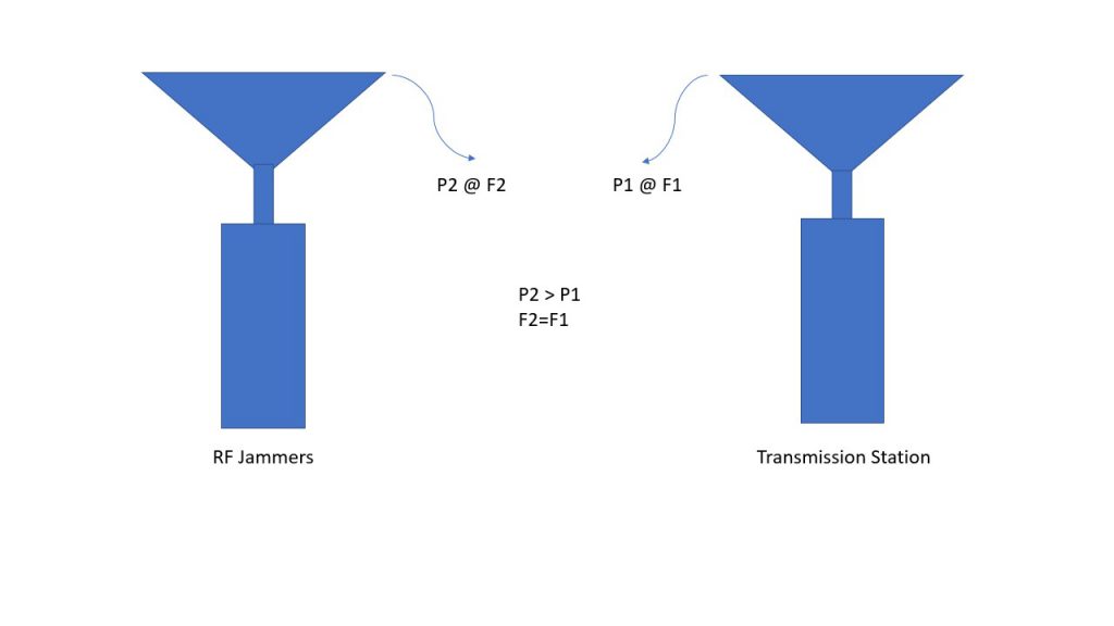
As mentioned above, function of RF signal jammer is to insert an interference signal into the radio communication frequency in such a way so that actual signal (i.e. wanted signal) is completely submerged by the RF interference. The effect of jamming signal depends upon J/S ( Jamming to Signal ratio ), interleaving, modulation type, channel coding technique of the target system. Jamming to Signal ratio can be expressed by the following equation.
J/S = (Pj * Gjr * Grj * Rtr2 * Lr * Br)/(Pt * Gtr * Grt * Rjr2 *Lj * Bj) Where,
| Pj= | RF Jammer Power |
| Pt= | Transmitter power |
| Gjr= | Antenna Gain from Jammer to the receiver |
| Grj= | Antenna Gain from Receiver to the Jammer |
| Gtr= | Antenna Gain from Transmitter to the receiver |
| Grt= | Antenna Gain from Receiver to Transmitter |
| Br= | Communications receiver Bandwidth |
| Bj= | Jamming Transmitter Bandwidth |
| Rtr= | Range between communication transmitter and receiver |
| Rjr= | Range between Jammer and communication Receiver |
| Lj= | Jammer Signal Loss, this includes polarization loss |
| Lr= | Communication signal Loss |
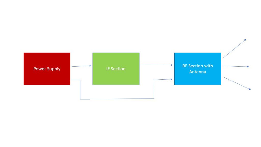
Mobile Jammer Block Diagram
As mentioned in the mobile jammer block diagram above, mobile jammer consists of three main parts viz. power supply, IF section and RF section. Power supply section usually provides needed DC voltages to IF section and RF section. IF section generates IF frequency by tuning VCO module as desired. VCO is tuned by reference oscillator signal. RF section converts IF frequency to the RF frequency by using RF upconverter. This RF upconverted frequency is amplified using RF power amplifier and tra smitted using suitable RF antenna.
RF Jammer Supplier
Here in MentariSetia, we aim to provide you with better protection against intrusion or unwanted tapings. We assure your privacy is protected and your status anonymous according to your request


One comment
Hi, this is a comment.
To get started with moderating, editing, and deleting comments, please visit the Comments screen in the dashboard.
Commenter avatars come from Gravatar.